Multiplexer is a combinational circuit that has maximum of 2n data inputs, ‘n’ selection lines and single output line. One of these data inputs will be connected to the output based on the values of selection lines.
Since there are ‘n’ selection lines, there will be 2n possible combinations of zeros and ones. So, each combination will select only one data input. Multiplexer is also called as Mux.
4×1 Multiplexer
4×1 Multiplexer has four data inputs I3, I2, I1 & I0, two selection lines s1 & s0and one output Y. The block diagram of 4×1 Multiplexer is shown in the following figure.
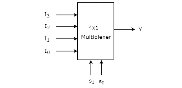
One of these 4 inputs will be connected to the output based on the combination of inputs present at these two selection lines. Truth table of 4×1 Multiplexer is shown below.
| Selection Lines | Output | |
| S1 | S0 | Y |
| 0 | 0 | I0 |
| 0 | 1 | I1 |
| 1 | 0 | I2 |
| 1 | 1 | I3 |
From Truth table, we can directly write the Boolean function for output, Y as
Y=S1′S0′I0+S1′S0I1+S1S0′I2+S1S0I2Y=S1′S0′I0+S1′S0I1+S1S0′I2+S1S0I2
We can implement this Boolean function using Inverters, AND gates & OR gate. The circuit diagram of 4×1 multiplexer is shown in the following figure.
We can easily understand the operation of the above circuit. Similarly, you can implement 8×1 Multiplexer and 16×1 multiplexer by following the same procedure.
Implementation of Higher-order Multiplexers.
Now, let us implement the following two higher-order Multiplexers using lower-order Multiplexers.
- 8×1 Multiplexer
- 16×1 Multiplexer
8×1 Multiplexer
In this section, let us implement 8×1 Multiplexer using 4×1 Multiplexers and 2×1 Multiplexer. We know that 4×1 Multiplexer has 4 data inputs, 2 selection lines and one output. Whereas, 8×1 Multiplexer has 8 data inputs, 3 selection lines and one output.
So, we require two 4×1 Multiplexers in first stage in order to get the 8 data inputs. Since, each 4×1 Multiplexer produces one output, we require a 2×1 Multiplexer in second stage by considering the outputs of first stage as inputs and to produce the final output.
Let the 8×1 Multiplexer has eight data inputs I7 to I0, three selection lines s2, s1& s0 and one output Y. The Truth table of 8×1 Multiplexer is shown below.
| Selection Inputs | Output | ||
| S2 | S1 | S0 | Y |
| 0 | 0 | 0 | I0 |
| 0 | 0 | 1 | I1 |
| 0 | 1 | 0 | I2 |
| 0 | 1 | 1 | I3 |
| 1 | 0 | 0 | I4 |
| 1 | 0 | 1 | I5 |
| 1 | 1 | 0 | I6 |
| 1 | 1 | 1 | I7 |
We can implement 8×1 Multiplexer using lower order Multiplexers easily by considering the above Truth table. The block diagram of 8×1 Multiplexer is shown in the following figure.
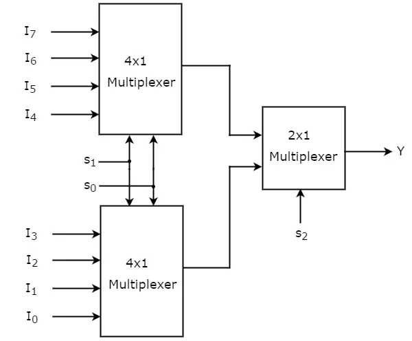
The same selection lines, s1 & s0 are applied to both 4×1 Multiplexers. The data inputs of upper 4×1 Multiplexer are I7 to I4 and the data inputs of lower 4×1 Multiplexer are I3 to I0. Therefore, each 4×1 Multiplexer produces an output based on the values of selection lines, s1 & s0.
The outputs of first stage 4×1 Multiplexers are applied as inputs of 2×1 Multiplexer that is present in second stage. The other selection line, s2 is applied to 2×1 Multiplexer.
· If s2 is zero, then the output of 2×1 Multiplexer will be one of the 4 inputs I3 to I0 based on the values of selection lines s1 & s0.
· If s2 is one, then the output of 2×1 Multiplexer will be one of the 4 inputs I7 to I4 based on the values of selection lines s1 & s0.
Therefore, the overall combination of two 4×1 Multiplexers and one 2×1 Multiplexer performs as one 8×1 Multiplexer.
16×1 Multiplexer
In this section, let us implement 16×1 Multiplexer using 8×1 Multiplexers and 2×1 Multiplexer. We know that 8×1 Multiplexer has 8 data inputs, 3 selection lines and one output. Whereas, 16×1 Multiplexer has 16 data inputs, 4 selection lines and one output.
So, we require two 8×1 Multiplexers in first stage in order to get the 16 data inputs. Since, each 8×1 Multiplexer produces one output, we require a 2×1 Multiplexer in second stage by considering the outputs of first stage as inputs and to produce the final output.
Let the 16×1 Multiplexer has sixteen data inputs I15 to I0, four selection lines s3to s0 and one output Y. The Truth table of 16×1 Multiplexer is shown below.
| Selection Inputs | Output | |||
| S3 | S2 | S1 | S0 | Y |
| 0 | 0 | 0 | 0 | I0 |
| 0 | 0 | 0 | 1 | I1 |
| 0 | 0 | 1 | 0 | I2 |
| 0 | 0 | 1 | 1 | I3 |
| 0 | 1 | 0 | 0 | I4 |
| 0 | 1 | 0 | 1 | I5 |
| 0 | 1 | 1 | 0 | I6 |
| 0 | 1 | 1 | 1 | I7 |
| 1 | 0 | 0 | 0 | I8 |
| 1 | 0 | 0 | 1 | I9 |
| 1 | 0 | 1 | 0 | I10 |
| 1 | 0 | 1 | 1 | I11 |
| 1 | 1 | 0 | 0 | I12 |
| 1 | 1 | 0 | 1 | I13 |
| 1 | 1 | 1 | 0 | I14 |
| 1 | 1 | 1 | 1 | I15 |
We can implement 16×1 Multiplexer using lower order Multiplexers easily by considering the above Truth table. The block diagram of 16×1 Multiplexer is shown in the following figure.
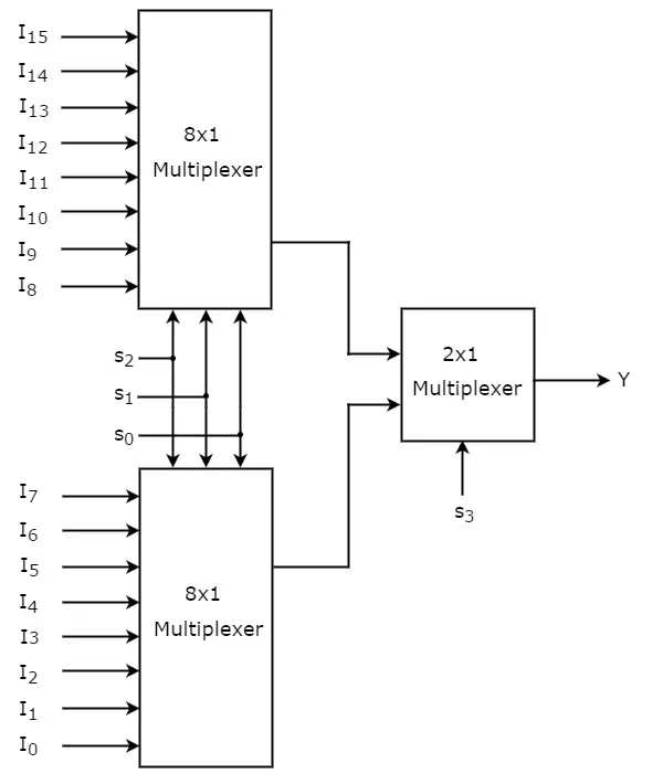
The same selection lines, s2, s1 & s0 are applied to both 8×1 Multiplexers. The data inputs of upper 8×1 Multiplexer are I15 to I8 and the data inputs of lower 8×1 Multiplexer are I7 to I0. Therefore, each 8×1 Multiplexer produces an output based on the values of selection lines, s2, s1 & s0.
The outputs of first stage 8×1 Multiplexers are applied as inputs of 2×1 Multiplexer that is present in second stage. The other selection line, s3 is applied to 2×1 Multiplexer.
· If s3 is zero, then the output of 2×1 Multiplexer will be one of the 8 inputs Is7 to I0 based on the values of selection lines s2, s1 & s0.
· If s3 is one, then the output of 2×1 Multiplexer will be one of the 8 inputs I15 to I8 based on the values of selection lines s2, s1 & s0.
Therefore, the overall combination of two 8×1 Multiplexers and one 2×1 Multiplexer performs as one 16×1 Multiplexer.